01 Overview
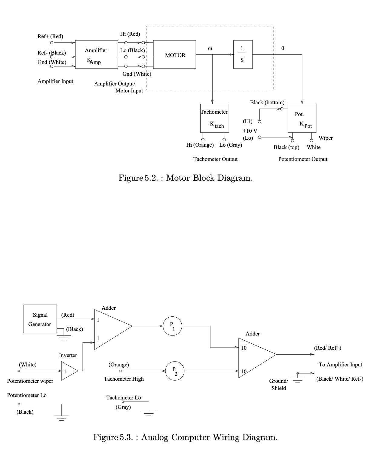
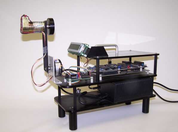
The plant has two sensors measuring the pendulum angle (θp) and the reaction-wheel angle (θr), and a single actuator — a motor mounted at the end of the arm that spins a flywheel. Because the only way to torque the pendulum is by accelerating the wheel, the system is underactuated: one control input must regulate two coupled degrees of freedom. The goal was to stabilize the pendulum at its unstable inverted equilibrium and keep it there under external pushes.
02 Modeling
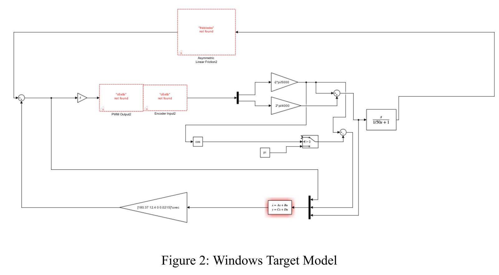
I derived the equations of motion from the Lagrangian, then linearized the dynamics into state-space form about the inverted operating point. We also produced a mathematical proof that the linearized, frictionless closed loop is stable in the inverted position — the analytical backbone the controllers were designed against. Wheel velocity was reconstructed from the angle sensors via an approximate continuous-time derivative.
03 Four controllers
Two-state feedback
A PD-style full-state controller via pole placement that regulates only the pendulum angle. Ignoring the rotor leaves its velocity unconstrained, so the wheel saturates and the system is hard to keep stable.
Three-state feedback
Adding rotor velocity as a third state and pulling its eigenvalue into the left-half plane gave dramatically better authority — the most robust controller of the four.
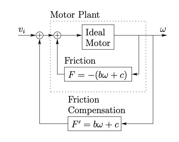
Friction compensation
Modeled friction as a linear function of speed and identified its coefficients experimentally: with the controller removed, I swept reference signals and let Simulink counteract friction, mapping control effort to speed. This stopped the wheel from over-compensating arm motion.
Decoupled observer
Since the internal states can't all be measured directly, I built a state observer and decoupled the 4-state design into two 2-state observers by zeroing cross terms — which also rejected sensor noise. A convergence proof shows the estimation error decays to zero.
As an extension I also prototyped an energy-based swing-up: classifying motion into four cases by the signs of sin(θp) and θ̇p, then driving the wheel to pump energy into the arm until it reached a height where the stabilizing controller takes over.
04 Results
Controllers were ranked by robustness — the largest pulse and sustained disturbance each could absorb before losing control. The three-state full-state-feedback design won, withstanding roughly:
05 Figures